MODEL 2200SLE SCANNED LASER OSL EXCITER
Among the many problems faced in dosimetry of natural mineral materials
is the often large grain-to-grain variation of TL/OSL properties, including
the presence of poorly-bleached grains all of which affects dosimetry when
an assemblage of grains is measured together (see for example, Roberts,
et al., 1999) . Duller, et al. (1998) have described a laser scanning
OSL detector system for the Risø reader that permits irradiation
and heating of many grains at once, and individual readout for characterization
of grains and dosimetry. We have developed a simple scanner of this
sort for our model 2200 OSL reader system, using new subminiature
galvanometer servos from Cambridge Technology (Cambridge MA) in an x-y
scanner mount. The field of scan is 13 mm square. The beam
from a 10 mW green diode pumped solidstate laser, power-, and temperature
stabilized , with optics to focus it down to about a 10 micron diameter
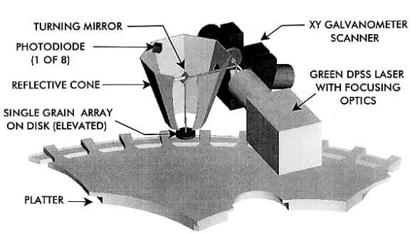
spot , is directed into the galvo scanner, then reflected down onto the
sample disk by a 8 mm by 12 mm turning mirror at 45 degrees. A segmented
octagonal cone reflector, made of thin glass sheet with magnesium fluoride
protected aluminum coating, collects light from the sample and efficiently
couples it to the PMT. The 10 mm sample disk contains an array of
one hundred 300 micron diameter sample wells on 600 micron centers to contain
the grains, together with orientation holes. The sample array disks
are precision machined of aluminum alloy. Other sample arrays can
easily be accommodated; in fact, we plan to make available disks with a
smaller number of 1 mm diameter wells to hold multiple grain aliquots when
they are desired. A dithering mode has been planned for scanning
extended areas. (In fact, OSL imaging should be possible!)
A series of radial scans is made from outside the disk inward till the
edge is detected, in order to establish the center position and scale of
the sample disk (without exposing the samples to the laser). The
reflection off the disk is detected by a silicon photodiode. Once
that is determined, the beam is scanned in an arc to find the postion of
the orientation holes near the edge. The centers of these two holes
are precisely determined and the center and angular orientation of the
sample hole array is computed. With this information the position
of individual grains may be calculated. We find edges by first filtering
the reflected signal with the beam profile, then taking the first derivative
to show a gaussian peak across the edge transition. The peak is found
(actually the centroid of the transition), and the coordinates at this
point are a very good measure of the edge position. Since
these galvanometers require no holding current, and the position-finding
scans are fairly slow (compared to the 500 Hz raster scans possible with
these devices), there is very little temperature rise to cause drift of
the built-in position sensors (less than 0.05%of scan/C total zero and
full scale drift). 12-bit x-y position information is applied to
the servo controllers for a 3 micron position resolution. The total
thermal drift over the course of measurements of grains on a sample disk
is well under 20 microns. A set of test data using a special test
disk is included with the command specification document referenced below,
and this is plotted to give an idea of pointed accuracy. This device
is designed to be compatible with the 1100-series readers as well. The
entire control function is contained in the microcontroller, without need
of the host computer, to make the instrument entirely platform-independent.
There is sufficient firmware memory (up to 512K bytes) to accommodate an
extremely sophisticated control program, and the program can be upgraded
in the field. Communication with the host computer is by a high speed
serial channel (up to 57,600 baud).
For flexibility, the laser scanner is packaged in two units. The
optical head contains the laser, galvanometers, and light collection optics.
This mounts on the 2200 cover (or 1100 lid), and the PMT housing mounts
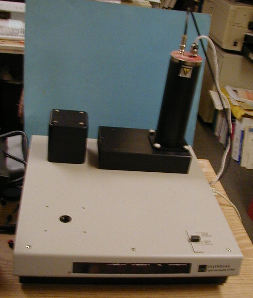
on it in turn. The size is 125 x 200 x 50 mm. The second unit
contains the control electronics and power supply, in a package 150 x 200
x 80 mm.
The command language for the 2200SLE
may be viewed in .pdf format.
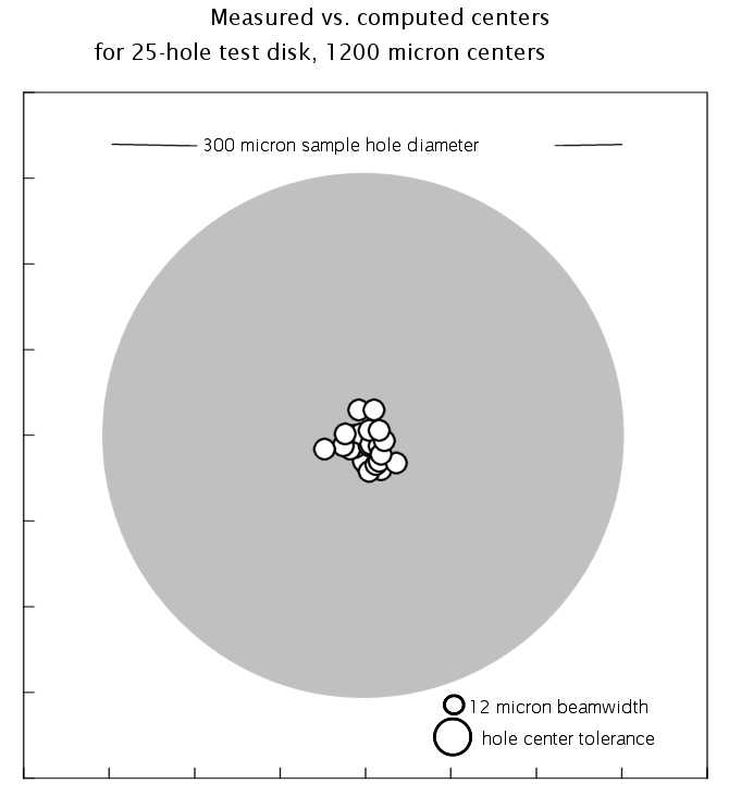
As an illustration of the precision of determining the orientation of the sample disk, and the accuracy of pointing the laser beam at the sample holes, we had special test disks made with 25 through holes covering the area of the usual 100 hole array. Because the beam is directed straight down at the disk, it is difficult to distinguish the bottom of a shallow sample hole from the top surface of the disk by reflection. With through holes, and black tape beneath, the test hole centers are found in precisely the same way as the orientation holes--the beam is scanned outwards in four directions from the computed center to detect the hole edges, and the actual center then is determined. The results are shown in the figure below. For the 25 test holes, the average deviation of the computed x coordinate from the actual center was 0.4 +/- 7.9 microns, while the y deviation was -6.5 +/- 8.0 microns. To put this in perspective, the machining tolerance on the location of the hole centers was +/- 12 microns. (The disk obviously meets the tolerance specification--we are very pleased with the fabricator!) The beam diameter at the 1/e2 point is 12 microns. Please note that ONLY the location of the orientation holes is required. It is completely unnecessary to measure hole centers as one goes along to perform a running correction, or to pre-measure all the holes in a particular disk, as do our competitors at Risø. Our method is similar to the Risø procedure 1 in Truscott, et al., Radiation Measurements 32, 447 (2000). Their discrepancies were x = -28 +/- 19 and y= 1 +/- 21 microns. Only by measuring the holes in a disk before loading with sample grains , their procedure 3, were they able to get accuracy comparable to ours. One reason for our ease of getting high accuracy is the use of a turning mirror. It makes the geometry extremely simple. Risø illuminates at a 45 degree angle, and the beam disappears from view of the detector when it falls into a hole or is off the disk edge. The computations are much more complex, and extremely sensitive to variations in disk height and tilt. Because the beam must remain focused over a 7mm range (the width of a disk at 45 degrees), their optical path is necessarily long, making their instrument quite bulky, and requiring factory installation. Our optical path is 125 mm, making possible excellent focusing with a simple planoconvex lens. The Daybreak 2200SLE has a small optical head that secures to the 2200 reader using four screws. No alignment is required for installation. The turning mirror does exact a price, reducing the signal by about 20 per cent. However, our overall detection efficiency is higher than our competition. Another advantage is speed: they use encoded motors to move mirrors while our fast closed loop-control galvanometers actually can raster scan the disk at 500 Hz! We do allow a lengthy 20 msec to allow the beam position to stabilize between sample holes, or any other large movement, simply because we were being conservative. Because of this speed, we do redundant measurements for finding the disk orientation, acquiring the disk in about 12 seconds rather than the minute or more with the Nordic system. This probably gives you an extra hour's work accomplished each day! Did we mention that our price for the 2200SLE is one half that of the competition for equal or better performance, and other advantages as seen above?
FUTURE PLANS
Impressed by the power of the microprocessor we chose for this project
and its ease of programming, we are about to adopt it for all our products.
What this means for the 2200 reader and 2200SLE is that the control box
for the 2200SLE will disappear, with the reader controller also controlling
the 2200SLE, and the power supply housed in the reader as well. A
new, smaller version of the galvo servo amplifier board is just now available,
and these boards, plus the DACs, will fit inside a slightly larger footprint,
but shorter, optical head, making the interface entirely digital (the optical
portion of the head by itself, comprising the two lasers, the xy galvos
and the conical reflector) is being redesigned for compactness and mounts
on and within a base only 75 x 125 x 32 mm). There also will be room
for a second laser module (870 nm, 10 to 100 mW maximum power depending
on choice of laser diode, 0-100 per cent modulation). The beam quality
from the laser diode will not be as good as the green DPSS laser's 12 micron
diameter, but will be about 25 x 50 microns, sufficiently good for the
application. We are thinking about a 3-filter changer attachment.
For those who wish to install the 2200SLE on non-Daybreak systems, a version
with controller/power supply case can be furnished.
Some views:
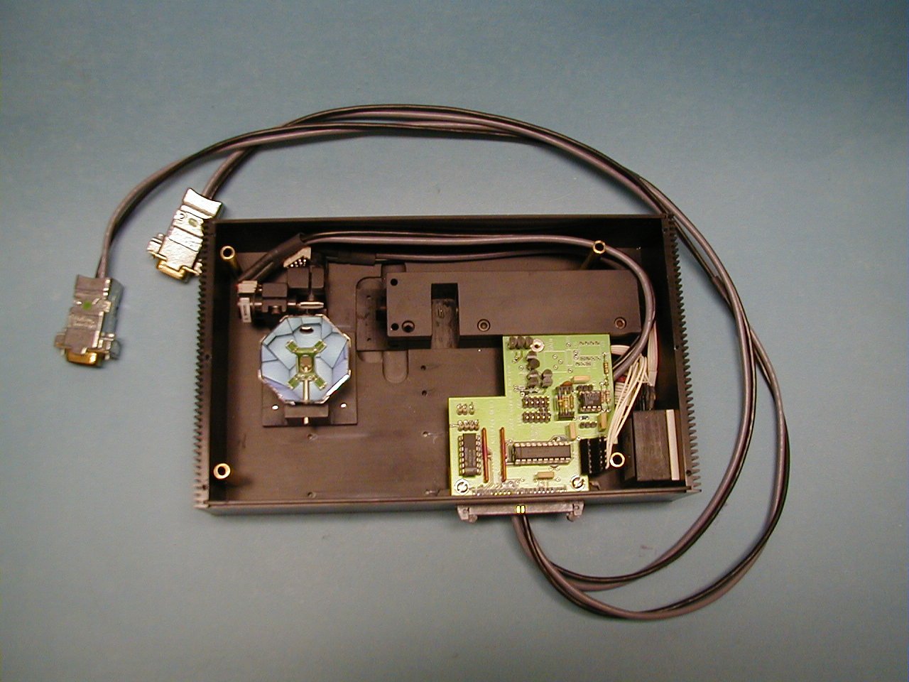
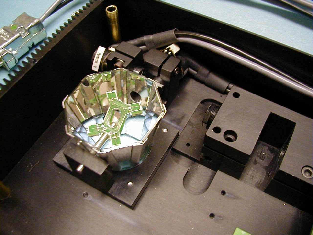
The interior of the optical head basic unit. The size is 13.5 x 22.6 x 5.1 cm.
The signal collection reflector with turning mirror and reflection monitor.
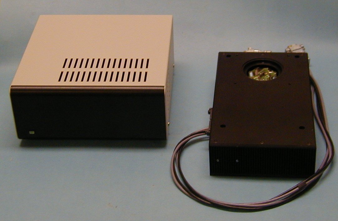
The entire unit consists of the optical head and the control box. The controller communicates with the host computer via a serial connection. The 2200 provides only the laser intensity control signal and enable for measurements; the controller provides these for orientation using the sample disk's edge and orientation holes.
The 2200SLE is shown mounted on a 2200 OSL reader.