1100IR/vis/P PULSE MODE OSL EXCITER
PRELIMINARY SPECIFICATION
The new Daybreak 1100IR/vis/P OSL exciter system is a complete timing module specifically for pulse mode OSL together with the LED light bars of the current 1100IR/vis. All-new very high speed driver electronics permit precision control of the power with pulse width limited only by the LEDs. As it happens, we have already been using the fastest LEDs available, and turn-on and turn-off times under 600 nsec make the emitters useful for pulses as short as 1000 nsec. The photodiode intensity monitors are new high speed devices (low capacitance) and the photodiode amplifiers have rise and fall times of less than 150 nsec. Pulse intensity is controlled directly by the control input, and not sampled and digitized for corrections to following pulses, as done by our competition. This makes it possible to perform fast LM-OSL measurements. The optical power for pulses up to 50 per cent duty factor (i.e., on 50 per cent of the time) is twice the CW level. So maximum pulse output is typically 300 mW/cm2 for IR (880 nm) and 100 mW/cm2 for blue (460 nm). These maximum powers are limited actually by the available system power, and we are looking into a separate adaptable power supply that will permit higher pulse powers without excessive device heating (the new class-G amplifier mode). It is estimated that achievable powers for 20 μsec pulses are 800 mW/cm2 for IR, 150 mW/cm2 for blue.
The timer section is a register-based array of six 16-bit counters arranged as a 32-bit period counter (16-bit counter with 16-bit prescaler), 16-bit OSL ON time counter, 16-bit delay time counter before starting the photon count, a 16-bit counter used for determining the length of photon counting after the delayed start, and a final 16-bit counter for allowing a set number of pulse cycles before ending the measurement sequence. A series of mode bits control the system configuration. All register and control data is transmitted on the 1100/2200 expansion bus (a 20-conductor cable with daisy-chained connection to various instruments), and is mapped onto 16 addresses 20-2Fh. The period counter prescaler may be configured also as a delay for triggering a laser pulse within the OSL on time (with the LEDs not switched on). It will be left to the user to build an interface to a laser controller, as aspects of pulsed laser OSL measurements are patented. Our design aim with this instrument is provide great flexibility for use in applications yet to be devised.
We have adapted the 530 photon amp/disc to be gated by the timer section, and can modify the IRIS4 counter module to be gated as well.
This OSL exciter system also is capable of CW/LM operation with the same characteristics as the 1100IR/vis.
We also are building in compatibility with the ORTEC MCS-pci fast multichannel scaler for time-resolved photon counting that resides on the computer PCI bus. This is an impressive, very flexible counter with counting up to 150 MHz, up to 65k channels, and with dwell time from 100 nsec to 1300seconds per channel. While this will be very useful for characterizing materials, the basic 1100IR/vis/P on its own is perfectly adapted for routine measurement. For further information, see:
www.ortec-online.com/pdf/mcspci.pdf
Note that the timer section and modes are completely controlled by software and not defined by front panel thumbwheel switches, as is our competition’s effort. In fact, the flexibility resulting from use of memory-mapped registers dates back to our first generation TL system’s computer interface, first shipped in 1980. This has been the basis of many advantages, not only in flexibility of measurement, but also in integration of additional instruments/accessories into the Daybreak systems. For example, the IRIS4 four-detector photon counter addresses 10-1Fh) and other (future) instruments, share the expansion bus.
Specification
LEDs
IR (880 nm): 20 LEDs in four banks of five mounted via beryllia substrates to copper blocks for efficient cooling, maximum power typically 150 mW/cm2 CW, 300 mW/cm2 pulsed (duty factor < 50 per cent). 2.5mm RG830 filter to suppress red emission at high power. Feedthrough with 3mm 7-59 and 2mm BG39 detection filtration at maximum IR CW power is typically less than 25 cts/sec. Rise/fall times typically 600 nsec at low currents, 300 nsec at maximum pulse current (1A).
Blue (460nm): 20 LEDs in four banks of five mounted via beryllia substrates to copper blocks for efficient cooling, maximum power typically 50 mW/cm2 CW, 100 mW/cm2 pulse (duty factor < 50 per cent). 2.5mm GG455 plus 2 mm BG39 filters to suppress feedthrough past the detection filters (U340), both in its UV bandpass and the unfortunate red transmission around 730nm. With 8mm U340, feedthrough is typically less than 10 cts/sec at maximum blue CW power. Rise/fall times are typically 600 nsec.
Photodiode monitors: reverse biased low capacitance (6 pF) device. Time constant of composite photodiode/photodiode amp and error amplifier/driver 150 nsec.
Important note: an upgrade kit for 1100IR/vis to the pulsemode version will be made available, involving replacement of the 1100IR/vis controller board and the photodiode intensity monitors.
TIMER SECTION
All data transferred under software control to counter registers and mode bits via 1100/2200 expansion bus.
Clock: 1 MHz crystal-controlled
32-bit period counter (a 16-bit counter plus 16-bit prescaler--up to 4000 seconds total duration)
16-bit pulse on time counter (up to 65 msec)
16-bit delay counter (up to 65 msec)
16-bit utility counter (up to 65k pulse cycles before stopping
16-bit gate timer (up to 65 msec photon counting after delay)
Alternatively, the counting gate can be left open till the next OSL pulse.
Note: there is a 1000 nsec delay built-in before and after the end of the photon count gate and the next OSL pulse.
Gate signal added to 530 amp/disc cable via pass through connector. Similar arrangement for IRIS4.
Compatibility with ORTEC MCS-pci for time-resolved measurements.
Modes: final configuration to be determined, based on eight bits of data, includes CW mode.
PHYSICAL: as 1100IR/vis with separate timing pod
CONNECTORS: 20-pin 1100/2200 expansion bus in and out (daisychain connection), counting gate out, 530 amp/disc in and out (with gating), MCS 10-pin, 1100/2200 OSL control in, OSL optical head control out.
DAYBREAK 725
RED DETECTOR
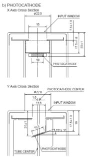
There recently has been a renewed interest in detection of red and near-IR TL and OSL. For quartz the interest mostly is the 640 nm emission, and for feldspar measurements circa 750 nm. The customary detector for this application is a cooled GaAs PMT, such as the Hamamatsu R943-02. These detectors have excellent quantum efficiency past 800 nm, but have small photocathodes, and high dark count rate unless cooled to the vicinity of –40C. Unfortunately, this requirement leads to an expensive, bulky and heavy package. We have a different approach, with a more affordable low dark noise detector that is useful past 750 nm and DOES NOT REQUIRE COOLING! We can get these tubes specified to have less than 25 dark counts/sec, and may possibly be able to set a tighter specification. The first two devices we have used had 11 and 18 dark counts/sec at 25C respectively. It is a PMT that one might otherwise overlook because, of all things, it is a side window device, a descendant of the 70-year-old 931 type. The Hamamatsu R4632 has an opaque (reflection mode) photocathode inherently quieter that the usual transmission type end window PMTs, with an effective 8 x 24 mm active area. With a UV transmitting cylindrical lens mounted on its envelope, the effective size becomes 16 x 24 mm, about four times the area of the R943-02 10 x 10 mm. What is more, the latter PMT has a recessed reflective photocathode vignetted by the input widow of the PMT and the cooler, so that it cannot accept a wide input cone. Its photocathode is 19mm below the 22mm tube face aperture and 12mm below the 11 x 15mm internal aperture, and can fully accept only well-collimated light. Typical cooled housing flange-to-tube window distance is 50 mm, indicating f/5 optics at best: rather poor collection efficiency for a luminescence measurement application with an extended source.
Because of these geometric considerations, the efficiency of light collection from a wide angle extended source is estimated to be 5 or more greater for the humble R4632 than the sexy R943-02. This is important because of the lower QE of the R4632, as shown in the two figures below.
R4632 spectral response
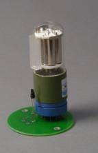
The R4632 with lens is shown here mounted in the 730 socket. There is a green LED for calibration along side (its intensity is reduced by a shrink tubing wrap). The photocathode of this PMT is tilted, with one side almost in contact with the inside of the envelope, and other (further into the PMT structure) obscured only by a wire focusing grid.
For comparison:
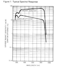
R943 photocathode configuration R943-02 spectral response
Taken all in all, for a luminescence extended sample, our R4632 detector has an overall detection efficiency no worse that one half of the much more expensive GaAs PMT system at 750 nm, and is more efficient at 650 nm.
We have configured the detection optics for maximum throughput into a 10 mm aperture at the photocathode using a pair of UV-transmitting acrylic fresnel lenses (50 per cent transmission at 270 nm). These are f/0.7 optics with a 25 mm spacing between for inclusion of a filter stack up to 23mm thick. The sample disk is roughly collimated by the first lens so that interference filters can be used without degradation of bandpasss characteristics due to off-axis rays. The second lens roughly images the sample disk onto the photocathode.
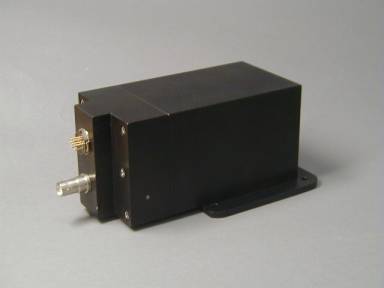
The detector housing is compact, and includes a 530 amp/disc. It is interchangeable with the standard 720 end window PMT housing with only a change of high voltage setting.
Physical
Dimensions: housing 7 x 7 x 16 cm
Weight: 750 g
Standard Daybreak mounting flange
Connectors: SHV (high voltage), 7-pin Amphenol-type hex (amp/disc)
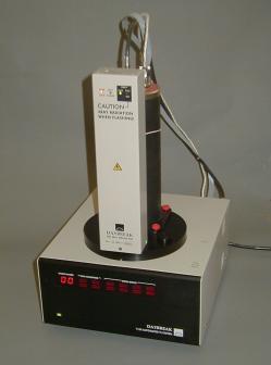
We have a new irradiator that in many cases can replace the traditional beta source where computer control of doserate is useful, and where safety and regulatory issues make radioactive sources unattractive. The prototype was developed for the irradiated foods application where the standard comparison dose is 1kGy. With 50μ Al and 40μ Be filtration, the achieved doserate at maximum voltage and current (40kV at 100 μA) from this device was 1.1 Gy/sec and +/- 3 per cent uniformity over a 10mm sample. The uniformity can be improved by increasing source-to-sample distance, or by limiting the sample-covered diameter to 8mm (as is often standard practice in sample preparation nowadays). The production version has an integral doserate monitor ( photodiode with scintillator), digital display of HV, current, control voltages and monitor current. This subminiature x-ray source with tungsten target includes the HV power supply in a package 27cm high x 6.5cm x 4cm, total weight 400g. The 1100 version (780) has a Be window; the 2200 version (781) has no vacuum window, but increased Al filtration. We are considering a version that includes an alpha irradiator. Filtration is easily changed in light of recent data about the variation of doserate with materials if low photon energy x-rays are not sufficiently filtered out. A photo of the prototype mounted on an 1100 is shown here.
 At
the suggestion of a user who plans to purchase this x-ray irradiator
(to go on
a 2200 OSL reader) for studies of radioluminescence as well as general
use, we
are designing an optical connection from irradiator to detector. The extremely small size of the x-ray tube
and its conical tip make it very simple to introduce a light guide to
the
detector PMT. It will be a bent solid fused silica rod 8-10mm diameter. Since its interface is with air, the numerical
aperture is very high compared to glass- or polymer-clad fibers, with
an
acceptance cone exceeding 90 degrees. Thus no additional optics are
required at
the irradiator side. We will put a
riser block to accept the light guide between the OSL light source and
the
detector filters, with a fresnel lens beneath to compensate for the
additional
distance from sample to detector. Thus collection efficiency will not
suffer. There will be a small turning
mirror at the detector end of the light guide, obscuring the sample
signal by
less than 10 per cent.
At
the suggestion of a user who plans to purchase this x-ray irradiator
(to go on
a 2200 OSL reader) for studies of radioluminescence as well as general
use, we
are designing an optical connection from irradiator to detector. The extremely small size of the x-ray tube
and its conical tip make it very simple to introduce a light guide to
the
detector PMT. It will be a bent solid fused silica rod 8-10mm diameter. Since its interface is with air, the numerical
aperture is very high compared to glass- or polymer-clad fibers, with
an
acceptance cone exceeding 90 degrees. Thus no additional optics are
required at
the irradiator side. We will put a
riser block to accept the light guide between the OSL light source and
the
detector filters, with a fresnel lens beneath to compensate for the
additional
distance from sample to detector. Thus collection efficiency will not
suffer. There will be a small turning
mirror at the detector end of the light guide, obscuring the sample
signal by
less than 10 per cent.
This has been worked out so far only for the 2200, since no vacuum window is required. Anyone seriously contemplating this type of measurement on an 1100 reader should realize that it will be a somewhat greater design challenge, but certainly doable.