|
|
PRODUCT DESCRIPTION
MODEL 1100 AUTOMATED TL/OSL SYSTEM
Note: due to the
prevalence of single aliquot methods with on-system irradiation required (and
the high cost of production), the high-capacity 1150 reader is no longer in
production. See below for the reasons why.
FEATURES
20
sample automated glow oven
on-board
computer with 19K memory
RS-232
serial interface to host computer
software
control of all operating parameters
exceptionally
flexible "soft machine"
single
photon counting with digital dead-time correction
electronic
PMT calibration with temperature compensated LED at photocathode
all
major analog signals digitized
full
size heating plate
1 to
25C/sec ramp rate with endpoints up to 700C
thermocouple
fault alarm
hardware
overtemperature interlock settable 400-700C
hardware
interlocks of HV and oven power
cooling
jet for fast cool down
low
volume glow oven for fast evacuation
very
compact, takes less than one square foot of bench space
firmware
definition of control function makes updates or reconfiguration economical
hardware
expansion capabilities
timer
control and power for auxiliary irradiator
RECENT
UPDATES
Support of quad photon counter for simultaneous
detection in four wavelength ranges
Support of alpha irradiator in 770 irradiation
shield/Be window
Improved light and irradiation shielding for crosstalk
reduction
Increased choice of detectors include two red-response
PMTs and the IRIS4 quad detector
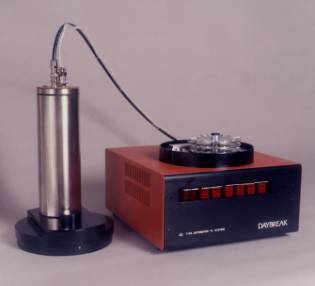 The Daybreak model 1100, introduced in 1987, and its
higher capacity sibling model 1150 (shown here), have combined the best
features of the original Daybreak modular TL system with an automated 20- or
57-sample glow oven and integrated microcomputer to produce a new generation of
thermoluminescence equipment. Coupled with Daybreak's classic TLAPPLIC or the
new FirstLight 2.0 for Windows software, and our extensive line of OSL exciters,
alpha counters and automatic and manual sample irradiators, you have an
integrated luminescence dating environment that will increase data production
dramatically. Please see the Product
Supplement for information about these models.
The 1100-series instruments present a combination of performance and
price that cannot be beaten, and has enough flexibility and expandability to
ensure that it never will. All of our
instruments are designed with the end user's needs in mind, based on 30 years'
experience in luminescence dating research and more than 100 Daybreak systems
installed throughout the world. For a
large capacity OSL-optimized system, see the new 60-sample OSL-only model 2200. This system uses the same control
electronics as the 1100-series, and most of the information in the present
document applies to it as well
The Daybreak model 1100, introduced in 1987, and its
higher capacity sibling model 1150 (shown here), have combined the best
features of the original Daybreak modular TL system with an automated 20- or
57-sample glow oven and integrated microcomputer to produce a new generation of
thermoluminescence equipment. Coupled with Daybreak's classic TLAPPLIC or the
new FirstLight 2.0 for Windows software, and our extensive line of OSL exciters,
alpha counters and automatic and manual sample irradiators, you have an
integrated luminescence dating environment that will increase data production
dramatically. Please see the Product
Supplement for information about these models.
The 1100-series instruments present a combination of performance and
price that cannot be beaten, and has enough flexibility and expandability to
ensure that it never will. All of our
instruments are designed with the end user's needs in mind, based on 30 years'
experience in luminescence dating research and more than 100 Daybreak systems
installed throughout the world. For a
large capacity OSL-optimized system, see the new 60-sample OSL-only model 2200. This system uses the same control
electronics as the 1100-series, and most of the information in the present
document applies to it as well
By designing our measurement systems around an
embedded microcomputer, we have accomplished a number of desirable
objectives. These include simplicity of
hardware, flexibility, autonomy from the host computer, increased reliability,
and perhaps most noticeable, a great reduction in physical size. Analog circuitry is reduced to a minimum
(just the heating plate temperature control loop, vacuum gauge amplifier, and
deadtime detection), and all major analog signals are digitized so that the
on-board computer can assume complete control.
This reduction in circuit complexity, and the use of highly complex
digital and data conversion building blocks, has the effect of increased
reliability due to fewer packages and interconnections and decreased size while
actually increasing functionality.
Compact mechanical design, and the use of high frequency switching power
supplies for system and heating plate power, together with the small size of
the electronics (only one sixth the printed circuit board space for the
equivalent function of the original modular TL system), has led to an
extraordinarily compact system size: 27 cm wide, 29 cm deep, 14 cm high, plus a
7.5 cm diameter by 23 cm high PMT housing.
In doing this, we have paid considerable attention to modular
construction techniques to ensure easy access for service and adjustment.
Since all control functions are implemented in
firmware, with a rich set of control codes, a great degree of flexibility is
possible and most future updating may be done with only a change of firmware or
host computer software.
Expansion capability has been built in as well, since
we fully expect future research to require greater resources. Up to 8 additional input/output ports (up to
128 input and output lines) can be added within the system architecture, and
there are 3 additional analog inputs available on the board.
Physical controls have been replaced by a ‘soft front
panel’ on the host computer. The utility TLCONSOLE is used for monitoring and
exercising system operation, and includes an always-visible context-sensitive
help window for sending commands. This
‘front panel’ display includes all status information in an easily read
form. The 1100-series instruments
continuously send 22-byte packets of information to the host computer for
continuously monitoring operation. (For
reassurance, we also put a status display panel on the instruments.) With this arrangement, even dramatic changes
in system configuration may be made economically. When taking data, a simplified set of status information is
displayed together with 'pushbuttons' and a real-time XY recorder-type display
of data as it is received.
The sample changing mechanism of the 1100 is simple
and reliable. It uses a floating sweep
arm to move samples on the turntable to and from a full-size heating
plate. Both flat (0.25 mm thickness and
above) and dished sample disks from 0.375 inch to 1.0 cm diameter are
accommodated (other diameters by special order). Fine grain and inclusion samples may both be analyzed due to the
smooth motion afforded by precision DC micromotors and worm gear drive. Dynamic
braking motor control ensures positional reproducibility. In the 1150, there are three such 20-sample
platters in a stack. These move
vertically to put the active platter on a level with the heating plate. (The sweep arm moves out of the stack to
allow this movement, so one sample position per platter is lost, hence the
57-sample capacity.) In both instruments the platters are removable for
loading, (A new version of the 801E
beta irradiator is presently in development that will accommodate these, and
with adapters, other types of platter—such as the Risø reader’s—without
unloading the sample disks.) Single
samples may also be measured. The small
volume of the glow oven (15 cm diameter by 1 cm deep) makes for fast
evacuation. The glow oven is designed
for use up to 700C for brief period. As
in the modular system, low heating plate power reduces cooling requirements.
Since the computer industry has been moving quickly
toward increased function, lower cost, and greater diversity, we have
configured the 1100 with serial interface (RS-232 at 9600 baud) for easy
communication with any computer, rather than a parallel interface as was used
in the original modular system.
SOME ADVANTAGES OF THE 1100 READER OVER THE COMPETITION
Full size heating plate
results in exceptional temperature control.
This is especially important for OSL measurements, as OSL sensitivity is
dependent on sample temperature, and preheat temperature must be reproducible.
Flexibility: the 1100
can do pretty much anything (a recent project to implement negative ramps comes
to mind). The timebase for OSL data
acquisition is completely adjustable, and the general ramp for TL allow the
data-taking scripts to describe nearly any measurement scheme imaginable.
Which brings up the new
FirstLight applications software suite (see website for more information).
The operation of the system
is defined primarily by its firmware, so updates to new accessories or new
measurement methods is simply implemented. A flexible expansion port permits
simple memory-mapped interface for new additions to the system family. This reduces the obsolescence
potential. Even 15-year-old systems may
be updated to the most recent configuration at minimal cost.
Four different detectors
are usable interchangeably.
The alpha/beta
irradiator (770 beta irradiator with two-position sample elevator, plus
optional alpha source below the Be window within the evacuable space) is the
most convenient means of making all the most useful methods of measurement.
Exceptional crosstalk
rejection. With the new OSL light
shield that hugs the sample platter closely (inspired by the newest version of
the 2200), the irradiation crosstalk is less than 0.05% dose delivered to
adjacent sample positions (less than ¼ that of our competition), and the OSL
crosstalk is very low (1000 seconds of full intensity blue OSL—more than 50 mW/cm2—removes
less than 4% of the OSL signal of an adjacent sample. The effect on the second closest samples is not measurable. The
competition does have a specification for this crosstalk)
Consistent sample
elevator height (2 positions) +/- 25um contributes to irradiation
precision. Our competition irradiates
on the sample platter. This leads to a
number of problems. First, the reproducibility of the delivered dose is
compromised. Second, the crosstalk is
increased. Third, any contamination of the platter with stray sample material
is also exposed and will show up as an inconsistent OSL background.
Many other advantages
are to be added as we think of them.
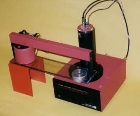
The 1100 is aimed specifically at geological dating
where automation is now a virtual necessity, and is intended for use with the
801 multiple sample alpha/beta irradiator, especially where irradiation times
are long. Many single aliquot
techniques now in use are easier and quicker when the irradiation is done on
the instrument, so that the samples need not be moved to an external
irradiator. The 770 beta irradiator
with a computer-controlled ‘trolley’ is shown here with a 1100. An optional irradiation port with a beryllium
window and two-position sample elevator is available for use with this irradiator. This irradiator moves the source away from
the 1100 when not needed to reduce the elevated dark count caused by close
proximity of the beta source to the PMT.
The major reason why the 1150 is no longer offered: Please note that because of the platter stacking in
the model 1150, the 770 may not be used with that model. It is possible to provide a special lid for
the 1150 that allows irradiation of the top platter only, without a sample
elevator; this degrades the exposure isolation between adjacent samples, and is
not recommended except under special circumstances.
 With
the addition of several OSL adapters, new detector choices such as the IRIS4
quad detector (for recording data in four wavelength bands simultaneously), and
the introduction of the 2000-series
family of dedicated OSL reader systems, a specification supplement has been
written to show our full range of instruments.
With
the addition of several OSL adapters, new detector choices such as the IRIS4
quad detector (for recording data in four wavelength bands simultaneously), and
the introduction of the 2000-series
family of dedicated OSL reader systems, a specification supplement has been
written to show our full range of instruments.
Note:
860 and 870-series OSL light sources are included for historical background
only. With the introduction of the 860-series of Xe lamp OSL light sources,
with the 1100FOI fiber optic illuminator, we are able to offer both IR and
visible stimulation with narrow passbands.
The new lower cost 870 Halogen OSL source has proven to yield excellent
power levels at narrow bandwidths, for example 20 mW/cm2 at the sample at 514
nm (34 nm passband. To complement these
instruments, we have enhanced the TLAPPLIC software to simplify handling of TL
and up to eight filter sets for OSL under computer control in the same batch program. (The new FirstLight 2.0 for Windows 95/98
is being released in 2001.)
Both
these OSL light sources have effectively been superseded by the 1100IR/Vis all
solid state OSL exciter. This is a
lower cost, zero maintenance instrument, and is our recommendation for general
purpose dating. This light source has been updated recently with double the
number of IR LEDs for increased output.
With blue LEDs (480 nm center wavelength), optical power levels in excess
of 50 mW/cm2 are possible,
30 mW/cm2 for green LEDs (515 cm).
As other wavelengths of high power LEDs become available, they may be
installed, since the ’light bar’ modules may be easily swapped. Maximum IR OSL power is now 100 mW/cm2. All solidstate light sources are
controllable 0-100 per cent power, and may be linearly modulated. It would be possible to use an arbitrary
I(t) should it prove useful, through a simple change in firmware. Papers on the
“light bar’ design and the various OSL light sources are available. Pulsed OSL with time domain data acquisition
is in design now (early 2006), and will involve swapping the CW/MOSL controller
board of the 1100IR/Vis with a pulsed current driver. Third party computer-hosted photon counting in the time domain is
now available at reasonable cost, and will serve as a very flexible means of
collecting data.
A
new stacking design for the detector/filter/illuminator configuration is now
being delivered, and all Daybreak products conform to this standard. Four thumbscrews fix the stack of components
to the top lid for quick and easy disassembly (e.g., for changing of filters).
In
the spring and summer of 1991 we embarked on a revision of the 1100's original
mechanical and electrical design to make possible the maximum commonality of
parts and assemblies between the family members, and leave enough room inside
to accommodate the added mechanism of the 1150 within the same size case. We
are now using smaller, lower power stainless steel solenoid valves for the
purge and cooling gas supplies and the first stage vacuum (bleed) valve, and a
significantly larger stainless main vacuum valve for even faster pumpdown. The gas plumbing has also been simplified by
use of a manifold to make maintenance easier. The water cooling built into the
original revision of the 1100 proved not to be necessary, so instead there is
fan-cooled heat sinking of the heater plate conductors. Various changes to make maintenance of the
changing mechanism more convenient likewise have been incorporated. The system power and heating plate power
supplies have automatic voltage selection, so these systems may be plugged in
anywhere in the world without alteration.
The main control board used in all our systems was also improved by the
addition of a second digital-to-analog converter for control of the OSL light
source intensity, a separate time base oscillator, watchdog timer, and an
irradiator driver. We have in mind as
well some future adapters, and have attempted to make their installation in
present instruments a simple task when they become available.
We
were quite excited about the 1100 when we introduced it back in 1987., but to
be honest, we did not consider it revolutionary It represented a distillation of the concepts pioneered by the
Daybreak modular TL system and our experience gained from the more than sixty
of those systems installed throughout the world. The capabilities built into these small packages are the natural
result of advances in the semiconductor and computer industries in the past
decade, and are a logical extension of our original system. Back in 1980, we had complete computer
control of the TL system, looking forward to automation. This degree of control, together with many
of the features designed into the modular system from its beginnings in 1978, has
lately been touted as something new and remarkable. We've had it for years without making much noise, and will
continue quietly to add features and new instruments. One thing we promise not
to change is our standard of quality, reliability, and customer service, and
our one-year warranty.
DETAILED SPECIFICATION
Firmware command set
The firmware architecture is that of a command-driven
state machine incorporating a generalized ramp whose controller is another
state machine. The actual ramping function
is timer-interrupt-driven and subject to hardware and software interlocks for
safety. Command codes from the host
computer consist of an ASCII character (the set '@' to '-', including the upper
case alphabetic characters, 32 altogether), and up to eight integer parameters (ASCII decimal strings) as
required by the control function.
The general form of a command is 'c xx yy ' where c is
the control character, and xx and yy are ASCII positive decimal integer
strings. <Space> characters are
used as delimiters, and the command string may end with any non-digit
character. The basic set of commands
for TL is shown below. A document
describing the full command set for all our instruments is available.
Command name Form Parameters
Set data space 'D' xx xx = 1-20
(C/point)
Set ramp rate 'R'
xx xx = 1-25 (C/sec)
Vacuum 'V'
xx xx = 0 (both off)
1 (bleed on, changes to main after
partial
evacuation)
2 (main on)
Purge 'P'
xx xx = 0 off
1 on
Cool 'C'
xx xx = 0 on
1 off
Ramp ('Go') 'G'
xx xx
= 0 stop
1 start
Preheat
('Wash') 'W' xx yy xx = 0-700 (temperature)
yy = preheat
time (seconds)
Stage 'S'
xx yy xx = 0-700 (temperature)
yy = stage time
(seconds)
Endpoint 'E'
xx yy xx = 0-700 (temperature)
yy =
hold time (seconds)
Cool-temp ('Low') 'L' xx xx =
temperature to start ramp for BG
Send ('Query') 'Q'
xx xx = 0 current status
1 last curve
HV 'H' xx xx = 0 high voltage off
1 high voltage on
Calibrate 'K'
xx xx = 0 calibrate off
1 on
Irradiate 'I'
xx yy xx = time (seconds)
yy=elevator
position
Advance 'A'
xx xx
= sample number. Advances to xx and loads sample
Home ('Base') 'B' goes
to sample 0, no load
Jump 'J'
xx goes to sample xx, no load
Reset ('Zero') ‘Z' initialize
controller
Setpoint
('at') '@' xx xx = 0-700 (setpoint temperature)
Oven 'O'
xx xx
= 0 oven off
1 oven on
A complete set of commands for OSL, including support
of multiple timebases and linear OSL intensity ramps, is also included. There is a suite of test commands for
checking out all aspects of the system.
Specialized commands for other accessories are added as necessary and an
easy change of firmware updates the hardware.
A complete description of the command language and FirstLight software
are available on our web site www.daybreaknuclear.com
Generalized ramp
The 1100 ramp consists of nine stages, most of which
encompass the optional preheat, stage, and hold cycles.
0: idle (ramp off, ambient temperature)
1: ramp up to preheat temperature
2: hold for preheat time
3: cool down to cool temperature (with jet)
4: ramp from ambient to stage temperature
5: hold for stage time
6: resume ramp up to end point temperature
7: end point hold time
8: cool down to cool temperature (with jet)
0: resume idle
Only stages 6, 8, and 0 are required. If preheat or stage hold time is zero, the
preheat or stage portions of the ramp cycle are bypassed. The ramp rate may be changed at any time
during the ramp.
Serial data format
A 44 character string is sent to the host computer
every second, or every data point, whichever comes sooner. The data is transmitted in hexadecimal ASCII
format, where the characters '0'..'9',
'A'..'F' map onto decimal integers 0..15.
Char 1-6 = photon count, most significant hex
digit first (for multiple detector systems, like
the IRIS4, this is
increased to 6 characters per detector)
7-8
= data point number (corresponding temperature depends
on data spacing)
9-10
= sample number (0..19). For the 1150,
this is (0..59) with positions 0, 20, 40
excluded
11-12
= ramp segment or stage number (see above)
13-16
= error code (0 = OK)
17-32
= 8 8-bit ADC channels for status display
0
= TMAX (hardware-set maximum temperature)
1
= T
2 = T error
3 = vacuum gauge
4 = vacuum gauge current
5 = ramp voltage
6 = livetime duty factor (for
deadtime correction)
7 = HV sense
33-40
= 32 status bits
41-43
= time since start of operation
<return>
1100-series Hardware Specifications
Temperature
control sub-system
Chromel-alumel thermocouple welded to heating plate
Ice
point compensation
Low-drift
TC amplifier
TC-open
alarm
Hardware
overtemp detector and interlock settable 400-700C
Hardware
and software interlock of heater power supply
Ramp
rate software settable 1-25C/second
Endpoint
software settable 0-700C (overridden by overtemp interlock)
Arbitrary
T(t) software controlled
Fast
response switching power supply for heater
1.45
inch long by 1.00 inch wide (active area) heating plate, channeled for
stiffness
Analog
temperature, temperature error, ramp (for checking) digitized to 8 bits
Photon
counter sub-system
EMI
9235QA quartz window bialkali PMT selected for low dark count
AMP/DISC:
4 nsec risetime, 6 nsec delay time discriminator with 20-1000mV threshold. ECL
differential
output capable of driving 50 ohm lines
Negative
high voltage (600-1600V), software enabled with hardware interlock
24-bit
photon counter
Analog
dead-time detector, software compensation
Temperature
compensated LED photon calibration with fiber optic light guide to
photocathode,
software
controlled
Easily
changed optical filter pack, 2.00 inch diameter.
Standard
pack supplied is Corning 7-59 + Schott BG-39 for TL or IROSL
Digitized
HV and dead-time compensation
Glow
oven
20-sample
changer with 7-second cycle time
Sample form: disks
flat or dished 0.010-0.060 inch thickness, 0.375-0.400 inch diameter (other
sizes
by
special order)
Software
control of atmosphere control solenoid valves
Two-stage
vacuum control (bleed and main)
Heating
plate cooling jet
Needle
valves for control of purge and cooling jet
Thermocouple
vacuum gauge with low-drift, low offset amplifier, digitized output
Low
volume for fast evacuation
Expansion
relief for heating plate to prevent flexure at high temperature
Purge/cooling
gas fitting: 0.25 inch Swagelock
Vacuum
outlet 1.0 inch tube stub for vacuum hose or 25mm ISO flange adapter
Microcontroller
2 Mhz
65F12AQ running FORTH kernel
8
kbytes RAM, 11 kbytes firmware in PROM
Very
fast, compact, control code
RS-232
serial interface at 9600 baud
Expandable
by 8 additional I/O ports, 3 analog inputs
Status
panel to show sample position number, state of valves, sample change, HV,
calibration,
OSL,
overtemp/TC fault, and power
Rear
panel
HV:
SHV connector
AMP/DISC/CAL:
7-pin Amphenol 126-series female connector
Serial
port: standard DB-9 female connector
Irradiator:
9-pin Amphenol 126-series female connector
OSL:
9-pin Amphenol 126-series female connector
Reset
switch
Power
input: IEC standard cord set, ON/OFF switch, fuse (X2)
General
Size:
10.5 inch wide, 11.7 inch deep, 14.6 inch high overall
Weight:
17.7 lb. (7.9 kg)
Power:
115-230 VAC 50-60 Hz, 150 VA, universal input
Auxiliary
irradiator control: 24V at 400 mA power available, timer output and two sensor
inputs
Designed
to meet UL, CSA, VDE, CE requirements